- All
- Product Name
- Product Keyword
- Product Model
- Product Summary
- Product Description
- Multi Field Search


Views: 0 Author: Site Editor Publish Time: 2026-09-29 Origin: Site


Deploying high-density IT infrastructure like AI clusters and liquid-to-chip GPUs demands rigorous thermal validation. Rushing this process without fully validating the Coolant Distribution Unit (CDU) and the secondary cooling loop invites catastrophic operational risks. Facility operators cannot rely on production IT equipment for Level 4 and Level 5 commissioning. Using live hardware for initial system testing introduces unacceptable risks of thermal events, fluid leaks, and severely delayed deployments. When a cooling loop fails during a live test, the resulting hardware damage and downtime derail the entire facility launch. The gap between theoretical CDU capacity and real-world performance must close before racking production servers. The solution requires deploying a precisely sized load bank for CDU testing. This equipment emulates rack-level thermal loads, fluid dynamics, and pressure drops safely. Simulating staged workloads prepares the entire cooling system for the complex thermal realities of actual silicon dies and Thermal Interface Materials (TIM).
Match the Secondary Loop Reality: Accurate sizing requires mirroring the exact fluid chemistry (e.g., PG25, treated water), flow rates, and pressure drops of the intended Technology Cooling System (TCS).
Approach Temperature is Critical: Sizing must account for every kelvin of approach temperature—working backward from the coldest water required by the chips to the warmest water supplied by the facility primary loop.
Simulate Beyond Steady-State: A properly specified load bank for CDU testing must be capable of simulating transient loads, staged workloads, and N+1 redundancy failover scenarios.
Telemetry Integration: Effective commissioning requires load banks that integrate seamlessly with Building Management Systems (BMS) to validate CDU control valve responses and pump curves.
Table of Contents
CDU commissioning requires testing pump capacity, heat exchanger efficiency, and control response under full load. Engineers verify stable coolant temperature, flow rate, and differential pressure while monitoring valve operation and pump adjustments to ensure reliable cooling performance.

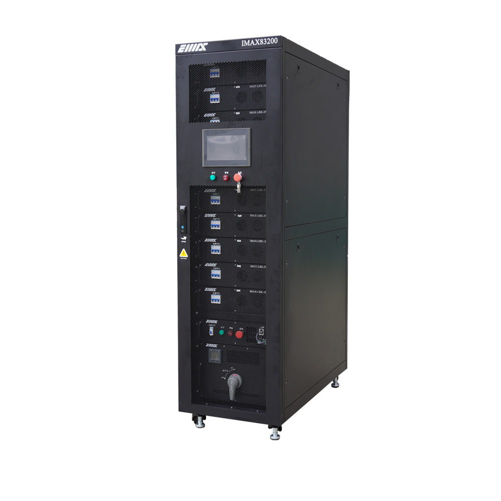
A Liquid-Cooled Load Bank replaces production servers during testing by converting electrical power into heat and transferring it directly into the TCS fluid loop. This allows engineers to safely validate CDU performance and optimize control logic before live IT deployment.
The load bank also verifies the complete cooling path from the CDU to rack manifolds and quick disconnects. Testing reveals potential issues such as pressure loss, uneven flow, trapped air, or leaks, ensuring sufficient coolant delivery to all server positions during operation.
Calculating the total required heat load involves mapping the CDU rated capacity against the expected rack density. If a facility plans to deploy ten racks at 120kW each, the CDU and the testing apparatus must handle a minimum of 1.2 MW of heat rejection. You must size the testing equipment to match or slightly exceed this peak thermal output. Exceeding the peak output slightly provides a safety margin, proving the heat exchanger transfers the load to the primary facility water without bottlenecking under worst-case scenarios.
Industry-standard resources, such as the Green Grid CDU sizing tool, provide excellent baseline calculations for fluid temperature and total heat rejection. These tools help operators define the exact kW requirements based on the specific thermal design power (TDP) of the targeted GPUs and CPUs. When establishing these baselines, always account for the heat added to the fluid by the secondary pumps themselves. Pump heat can marginally increase the total cooling demand, and ignoring it leads to undersized cooling infrastructure.
Future scalability dictates equipment selection strategies. Testing a massive 1.2 MW CDU does not require a single, monolithic testing unit. Facility teams often utilize modular 100kW or 200kW increments. Daisy-chaining modular units allows for granular testing of individual rack positions while collectively proving the total capacity of the central CDU. This modular approach provides flexibility for future facility expansions and varying rack densities across different data halls.
Target Rack Density (kW) | Number of Racks per CDU | Total IT Heat Load (kW) | Recommended Test Capacity (kW) |
|---|---|---|---|
50 kW | 10 | 500 kW | 550 kW (10% Margin) |
100 kW | 8 | 800 kW | 880 kW (10% Margin) |
150 kW | 10 | 1500 kW | 1650 kW (10% Margin) |
The test system must match the cooling loop’s required flow rate to accurately validate thermal performance. Because different coolants have different heat capacities, fluids such as glycol mixtures may require higher flow rates than water to remove the same amount of heat. The testing equipment must align with the CDU pump curve to avoid creating false performance results caused by excessive or insufficient hydraulic resistance.
The testing equipment must replicate the hydraulic resistance of actual server cold plates. Without matching the expected pressure drop, CDU pumps may operate under unrealistic conditions and fail to demonstrate true system capability. Adjustable valves allow engineers to simulate cold plate resistance, verify differential pressure control, and confirm that variable-speed pumps respond correctly under real operating conditions.
Approach temperature measures the heat exchanger’s ability to transfer energy between the primary and secondary cooling loops. The testing system must verify that the CDU can maintain the required coolant supply temperature under maximum load conditions. By simulating full thermal demand, engineers can confirm that control valves and heat exchangers respond accurately to temperature changes and maintain stable cooling performance.
Testing equipment must use the same coolant type as the production cooling system to ensure accurate results. Fluids such as PG25, treated water, or dielectric fluids have different thermal and hydraulic properties, affecting heat transfer and pressure performance. Using an incorrect coolant can produce misleading test data and fail to represent real operating conditions.
Load bank materials must be compatible with the facility’s cooling loop to prevent galvanic corrosion and fluid contamination. Incompatible metals can release particles that damage pumps, seals, and cold plates. Testing equipment should use suitable stainless steel or polymer components and be properly flushed before connection to avoid introducing contaminants into the system.
Coolant Type | Primary Application | Required Wetted Materials | Corrosion Risk Factor |
|---|---|---|---|
Treated Water (PG25) | Direct-to-Chip Cooling | 304/316 Stainless Steel, EPDM | Moderate (Requires Inhibitors) |
Ultra-Pure Water (UPW) | High-Density Micro-Channels | 316L Stainless Steel, PTFE | High (Aggressive Solvent) |
Dielectric Fluid | Single-Phase Immersion | Compatible Polymers, Viton | Low (Non-Conductive) |
Selecting the right physical configuration depends heavily on the facility layout and the specific goals of the commissioning phase. In-row or rack-mounted units slide directly into standard EIA racks. These units test specific rack manifolds, hose whips, and localized flow distribution. They provide highly granular data on how fluid behaves at the exact point of connection for future servers, making them ideal for pinpointing localized flow restrictions.
Conversely, large-capacity floor-standing units bulk-test the total capacity of massive perimeter CDUs. While they do not test individual rack whips, they apply massive thermal loads (e.g., 500kW to 1MW) from a single footprint. Testing in-row CDUs designed to distribute cooling to several adjacent racks often benefits from rack-mounted units. Large perimeter CDUs serving entire data halls operate more efficiently when tested with high-capacity floor-standing systems.
Configuration Type | Primary Application | Testing Granularity | Logistical Considerations |
|---|---|---|---|
Rack-Mounted | Testing in-row CDUs, rack manifolds, and individual hose whips. | High. Validates flow and pressure drop at the specific server position. | Requires racking multiple units. Higher setup time but precise local data. |
Floor-Standing | Bulk-testing large perimeter CDUs and total facility heat rejection. | Low. Validates total loop capacity but not individual rack distribution. | Easier to roll into place. Requires heavy-duty hoses and central connections. |
Modular load bank systems provide flexibility by allowing multiple units to be combined for different testing capacities. They are ideal for large-scale facilities with multiple data halls or future expansion plans. Fixed-capacity systems are simpler and cost-effective for single, specific testing requirements but offer limited scalability.
Modern load banks require advanced control and communication capabilities. PLC-based systems using protocols such as Modbus TCP, BACnet/IP, or SNMP allow integration with BMS and CDU controllers. Real-time data logging helps verify load responses, sensor accuracy, valve control, and overall system performance during commissioning tests.
Sizing a load bank for CDU testing represents a multi-variable engineering equation. Accurate sizing requires a deep understanding of total heat load, precise flow rates, exact pressure drop emulation, and strict fluid chemistry compatibility. Failing to account for any of these variables results in an incomplete commissioning process, leaving the facility vulnerable to thermal events and hydraulic failures when live IT equipment deploys.
When shortlisting a vendor, prioritize engineering accuracy over basic capacity. The selected equipment must match the exact differential pressure (ΔP) of your specific cold plates. It must guarantee wetted material compatibility with your chosen coolant, offer BMS integration for telemetry validation, and provide modular scalability to adapt to varying rack densities.
Execute the following steps to finalize your testing strategy:
Gather all CDU performance data sheets, focusing specifically on secondary pump curves and maximum heat exchanger capacity.
Obtain the exact IT cold plate specifications from your server OEM, including required flow rates, pressure drops, and fluid chemistry requirements.
Map out your facility primary water temperature profiles to establish the required approach temperature for the test.
Provide these three data sets to a specialized manufacturer to secure an accurately sized testing solution.
A: Air-cooled units reject heat directly into the surrounding room, testing CRAC units and ambient airflow. Liquid-cooled units reject heat directly into the CDU secondary fluid loop. This validates the liquid cooling infrastructure, including pumps, heat exchangers, and fluid dynamics, without heating the ambient air.
A: Flow rate is calculated using the total heat load (kW), the specific heat capacity of the coolant, and the target temperature differential (ΔT) between supply and return. Tools like the Green Grid CDU sizing tool assist in establishing these baselines accurately.
A: The CDU pumps must overcome the hydraulic resistance of the IT equipment. If the testing unit fails to simulate this total pressure drop across the cold plates, pump performance, variable speed drive response, and overall flow distribution cannot be accurately verified.
A: No. You must use the exact fluid specified for the production environment (e.g., PG25 or ultra-pure treated water). Using tap water alters the thermal transfer rates, invalidates performance data, and introduces contaminants that cause corrosion or biological growth.
A: It is the temperature difference between the primary cooling water entering the CDU and the secondary coolant leaving the CDU. Testing units verify the heat exchanger maintains this approach under full load, working backward from the coldest water the chips require.
A: By programming the testing unit to execute sudden, massive load steps, or by manually failing a primary CDU pump during operation. This allows operators to verify the backup pump engages immediately without exceeding critical thermal thresholds in the secondary loop.


