- All
- Product Name
- Product Keyword
- Product Model
- Product Summary
- Product Description
- Multi Field Search


Views: 0 Author: Site Editor Publish Time: 2026-09-29 Origin: Site


Untested power infrastructure creates massive operational vulnerabilities. A UPS system provides zero value if it fails to support the facility during an actual utility outage. Relying solely on internal UPS self-diagnostics or factory testing presents severe risks. You must validate performance under real-world, site-specific electrical stress. Project managers and facility directors require a definitive framework to plan, execute, and evaluate testing protocols. We will outline how to guarantee continuous power without jeopardizing live IT environments. By implementing these strategies, you can confidently verify your power train, isolate risks, and ensure standardized compliance across your entire critical infrastructure. Proper validation requires pushing the equipment to its absolute limits before it ever sees a live server load. This approach separates resilient facilities from those waiting for a catastrophic failure.
Timing is Critical: Post-installation load testing should occur no sooner than one week after deployment to ensure UPS batteries are fully charged, chemically stabilized, and ready for accurate capacity readings.
Holistic Validation: Effective testing requires simulating both steady-state and transient loads using a dedicated data center load bank to verify the entire power train across all functional design points.
Risk Isolation: Utilizing external, computer-controlled load banks prevents live critical infrastructure from being exposed to potential failure during the stress-testing phase.
Standardized Compliance: Adhering to IEEE standards and manufacturer specifications during testing is mandatory for maintaining warranties, generating baseline testing reports, and proving facility tier compliance.
Table of Contents
You must establish strict baseline requirements before initiating any testing sequence. The primary objective involves verifying output voltage stability, frequency regulation, and harmonic distortion limits under 100% rated load. Functional load testing remains absolutely necessary for proving system reliability. It involves pushing the UPS system through all functional points it was designed to handle under maximum stress.
These functional points include normal operation, battery mode, eco-mode, and static bypass transitions. Success criteria shift over the lifecycle of the equipment. Initial commissioning proves the design capacity meets site requirements and validates the installation quality. Periodic maintenance testing identifies component degradation, such as drying capacitors or failing IGBTs, before a catastrophic failure occurs.
Operators must monitor specific metrics during the test to confirm the system meets operational standards. A successful test requires the equipment to stay within tight tolerances regardless of the load applied.
Performance Metric | Standard Tolerance | Failure Indicator |
|---|---|---|
Voltage Regulation | ±1% of nominal output | Voltage sag during steady-state load |
Frequency Stability | ±0.1 Hz during operation | Inability to sync with bypass source |
Total Harmonic Distortion (THD) | <3% for linear loads | Excessive heat in transformers |
Static Bypass Transfer | <4 milliseconds | Dropped load during transition |
The cost of comprehensive testing is small compared with the impact of an unexpected outage. Live IT loads rarely provide stable, full-capacity testing conditions, while simulated loads allow engineers to safely verify UPS performance at maximum capacity without risking critical equipment.

AC load banks verify the complete UPS power path, including inverter, rectifier, and bypass performance. DC load banks test battery strings directly, providing accurate capacity measurements and identifying individual cell weaknesses. Both methods provide different validation data and are often required together.
Resistive load banks simulate purely active power with a 1.0 power factor. They play a key role in basic capacity verification and thermal stress testing. They convert electrical energy entirely into heat, testing the raw kilowatt (kW) output of the UPS system.
Reactive load banks simulate lagging or leading power factors. Combining both resistive and reactive elements is necessary to test the full apparent power (kVA) rating of the equipment. Modern IT server loads utilize switch-mode power supplies that create complex electrical draws. A combined approach accurately mimics these real-world conditions. Utilizing a proper Data Center Load Bank ensures your testing reflects actual server behavior rather than a simplified laboratory scenario.
You must delineate the boundaries between FAT and SAT. FAT validates manufacturing quality in a controlled factory environment using perfect grid power and ideal ambient temperatures. SAT validates the UPS within the site's specific electrical ecosystem, interacting with actual backup generators and facility grounding systems.
FAT cannot replace SAT. Shipping vibrations, installation errors, and site-specific switchgear integration introduce new variables that only manifest on-site. Project managers must understand this distinction to avoid false security. A UPS might pass FAT perfectly but fail SAT due to improper field wiring, mismatched breaker coordination, or environmental factors.
Shipping vibrations can loosen internal busbar connections.
Field wiring errors can cause phase rotation mismatches.
Site grounding issues can introduce common-mode noise.
Facility cooling may fail to handle the UPS heat rejection.
Generator synchronization may fail under actual load steps.
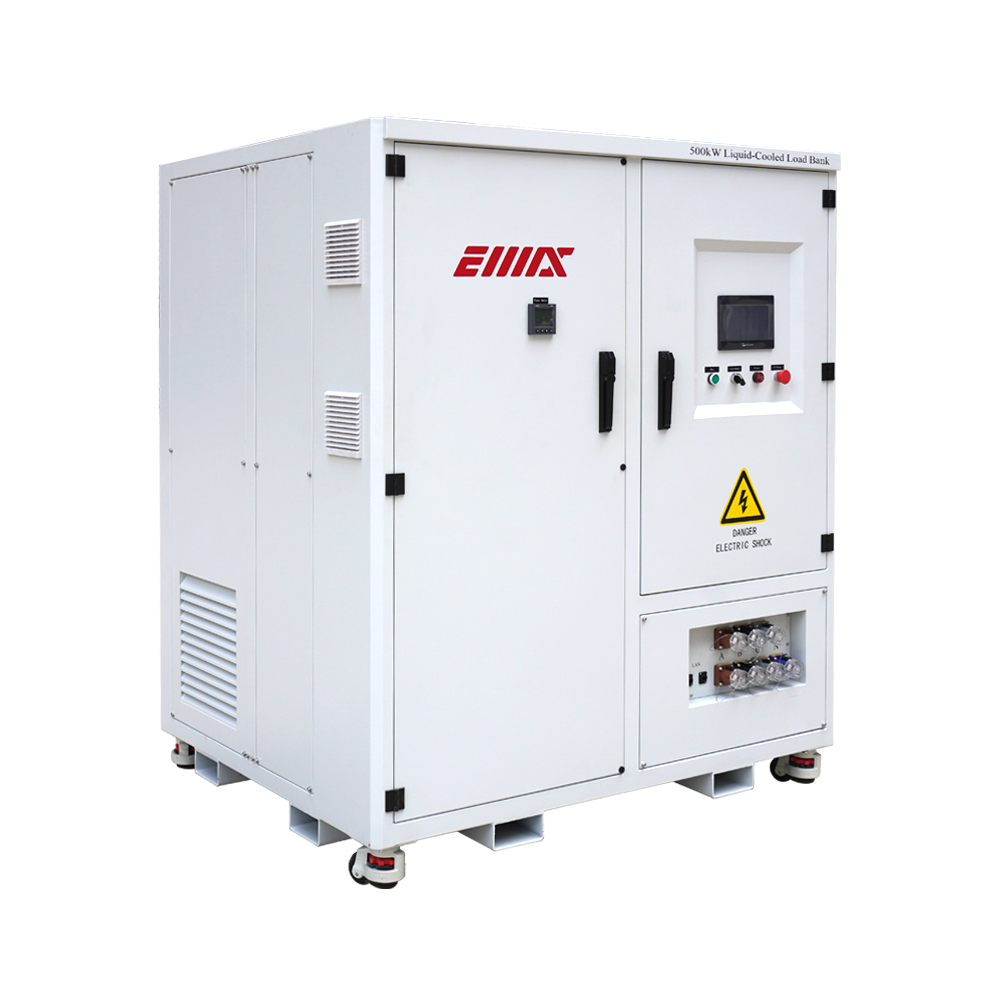
Before connecting external loads, complete visual inspections, torque checks, and system verification. Confirm cable integrity, breaker settings, ventilation, alarms, bypass functions, EPO circuits, and BMS communication to ensure safe operation.
Steady-state testing applies gradual load steps, such as 25%, 50%, 75%, and 100%, to verify thermal stability and component performance. Transient testing applies sudden load changes to evaluate UPS voltage recovery and dynamic response under real operating conditions.
Battery discharge testing confirms actual backup runtime and identifies weak cells. Measure cell voltage and internal resistance throughout the test to establish battery health and create a maintenance baseline.
Allow newly installed batteries sufficient stabilization time before testing. Waiting about one week enables proper float charging and cell equalization, ensuring accurate discharge test results and avoiding false failures.
Full-load testing generates significant heat that can overwhelm facility cooling systems. Proper exhaust routing, cable management, and temperature monitoring are required to prevent overheating, fire alarms, and equipment damage.
Establish clear emergency procedures before testing. Define abort steps, load removal processes, and personnel responsibilities to ensure safe UPS operation if abnormal conditions occur.
Complete detailed test documentation after execution. Reports should include performance data, thermal results, battery metrics, and pass/fail verification to support compliance, warranty claims, and future maintenance planning.
Testing procedures should align with recognized standards such as IEEE battery testing guidelines and ASHRAE thermal requirements. Compliance ensures reliable results, safety, and defensible commissioning records.
Choose vendors based on certifications, safety history, equipment capability, and reporting quality. Qualified providers should supply detailed test plans, risk assessments, data logging capabilities, and comprehensive final reports.
Executing UPS load bank testing is not an optional maintenance task. It remains the only empirical method to guarantee data center power resilience and avoid catastrophic outages. Facility and project managers must choose their testing parameters based on specific tier requirements, risk tolerance, and critical load profiles. By isolating risks and validating the entire power train, you secure the foundation of your critical infrastructure.
Audit your current maintenance schedules to identify gaps in site acceptance testing.
Define strict load parameters for all upcoming equipment deployments based on your facility tier.
Request detailed testing proposals and sample reports from certified, specialized vendors.
Establish a comprehensive baseline performance document to track future component degradation.
A: Perform testing annually for critical facilities. Conduct testing more frequently for aging battery strings or immediately following major repairs and component replacements to verify system integrity.
A: Testing must cover all design parameters. This includes normal operation, battery discharge mode, eco-mode, and seamless transitions to static bypass under full electrical load.
A: A resistive unit simulates active power with a 1.0 power factor. A reactive unit simulates real-world IT power factors, mimicking the complex electrical draw of modern servers.
A: Waiting allows battery chemistry to stabilize. It ensures a full float charge, which is absolutely necessary for accurate capacity readings and preventing false failures during the discharge cycle.
A: Yes, using isolated parallel systems. However, it is highly discouraged without strict fail-safes due to the severe risk of dropping the critical IT load if an anomaly occurs.


