- All
- Product Name
- Product Keyword
- Product Model
- Product Summary
- Product Description
- Multi Field Search


Views: 0 Author: Site Editor Publish Time: 2026-07-31 Origin: Site


Procurement decisions concerning electrical testing equipment often create a complex dilemma for facility managers. You must choose accurately between a standard AC Load Bank and a highly specialized RLC Load Bank. Over-specifying your testing equipment wastes valuable engineering resources unnecessarily. Conversely, under-specifying leads directly to catastrophic compliance failures during critical audits. Let us establish the technical baseline clearly. An RLC unit technically operates on alternating current. Yet, industry terminology uses "AC load bank" exclusively to describe standard resistive or resistive-inductive units. Meanwhile, "RLC" denotes precision testing units containing resistive, inductive, and capacitive elements. We wrote this article to provide a clear, engineering-driven framework. You will discover exactly how to select the correct equipment based on stringent compliance rules. We will also explore specific testing profiles extensively. This guide ensures your facility meets regulatory standards confidently.
Engineers must understand the equipment baseline thoroughly before executing certification tests. Standard testing units typically utilize pure resistive elements. These elements convert electrical energy into heat energy safely and efficiently. This thermal process allows operators to verify real power capacity, measured in kilowatts (kW). A purely resistive load applies a unity power factor of 1.0. This tests the prime mover, such as the actual diesel engine block.
Many commercial units also integrate inductive components. Inductors allow technicians to test lagging power factors. When we introduce inductive elements, we test the alternator's ability to handle reactive power. This capability is crucial for environments managing heavily motor-driven loads. Most facilities target a 0.8 lagging power factor during routine diesel generator runs.
We must also clarify the "RLC" acronym specifically. It stands for Resistive, Inductive, and Capacitive components. Adding a capacitive element changes the testing dynamic entirely. It allows facilities to simulate leading power factors accurately. Capacitive components simulate the leading power factors often generated by long cable runs or modern LED lighting arrays.
Furthermore, the capacitor creates a precise resonant circuit. During true resonance, inductive and capacitive reactances cancel each other out perfectly. This precise cancellation creates a zero-reactive-power state. Facilities face a specific business problem here. The decision is never about finding a universally "better" machine. Instead, you must align the chosen technology to your distinct regulatory testing mandates. You must verify what the local utility or safety inspector demands before proceeding.
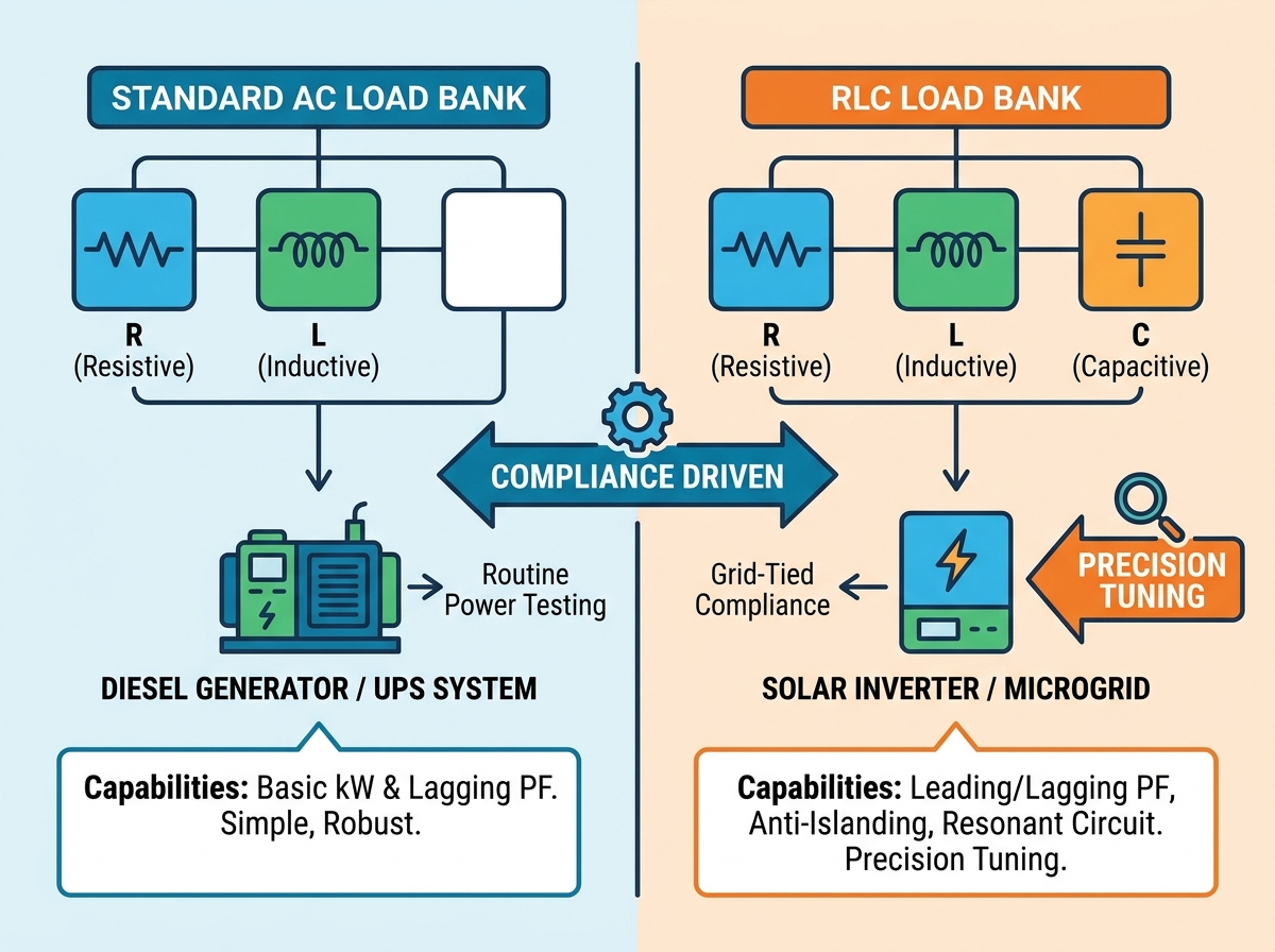
These traditional testing units deliver highly reliable, robust verification. They easily confirm the exact nameplate ratings of rotating generators. Regular operational use actively prevents diesel engine wet-stacking. Unburned fuel accumulates rapidly if generators run under extremely light loads. Applying a full thermal load burns off this dangerous accumulation effectively.
Operators also rely on them heavily for basic transient response testing. Technicians typically apply electrical load in specific progressive blocks. They might start at 25 percent, moving to 50, 75, and finally 100 percent of rated capacity. This step-loading verifies generator governors respond correctly to sudden voltage demands. You can apply sudden blocks of load to measure voltage drops accurately.
Operational simplicity remains a massive advantage for standard units. Technicians require minimal specialized training to operate them safely. Control systems typically apply step-loads using very straightforward interfaces. Operators flip a toggle switch, and heavy-duty contactors engage the internal resistors immediately.
However, you will encounter strict implementation limits eventually. Standard units cannot simulate leading power factors under any circumstances. They also cannot test the precise resonance conditions required today. Advanced grid-tied inverter testing absolutely requires both capabilities.
Primary applications include the following scenarios:
Advanced grid applications require a significantly higher level of engineering precision. Specialized units tune power factors exactly to user specifications. They handle both leading and lagging electrical loads seamlessly. They also match specific resonant frequencies perfectly during simulated grid failure events.
Grid-tied inverters face strict anti-islanding regulatory mandates globally. If the utility grid fails, the local inverter must shut down immediately. This critical safety disconnect protects utility workers repairing external power lines. Consider a local solar farm feeding power back into the municipal grid. If a falling tree severs the main utility line, the solar inverters must sense the voltage drop instantly. They must cease power production within milliseconds.
To test this mechanism in a laboratory, engineers use capacitive and inductive elements. They match the inverter's electrical output exactly. An RLC unit simulates a perfectly balanced local load environment. It effectively tricks the inverter into thinking the grid remains active. Once the local load perfectly matches the inverter output, technicians disconnect the main utility feed. The inverter should recognize the grid loss, even though the local load remains perfectly balanced. This specific process provides the ultimate stress test for internal safety sensors.
Implementation involves significant structural and operational realities. These precision systems feature high thermal and structural complexity. They require robust cooling mechanisms to protect sensitive internal capacitors. Operators need advanced PC-based software to manage intricate testing sequences. Modbus communications and specialized GUIs handle precision micro-step tuning exclusively.
Primary applications include:
When evaluating the Differences between RLC and AC load bank for testing, consider technical limits carefully. You must look far beyond basic kilowatt ratings. Standard models prioritize rugged simplicity and high durability. Specialized models prioritize micro-adjustments and rigorous environmental simulations. The comparative matrix below highlights the primary divergence points clearly.
| Technical Parameter | Standard AC Load Bank | Precision RLC Load Bank |
|---|---|---|
| Testing Capabilities | Real power (kW) and Apparent Power (kVA) tests | kW, kVA, and strict Resonant Frequency tuning |
| Power Factor Range | 1.0 unity or 0.8 lagging typically | Fully adjustable leading to lagging parameters |
| Scalability & Integration | Easily paralleled using straightforward setups | Complex integration requiring advanced synchronization |
| System Control Style | Manual toggles or basic step-load PLCs | Advanced PC-based GUI using Modbus protocols |
| Compliance Alignment | Standard local fire codes and building codes | Strict grid standards like UL 1741 and IEC 62116 |
Complex integration often requires dedicated fiber optic links between modules. This eliminates data latency during high-speed resonance testing. You can clearly see how each unit serves fundamentally different engineering purposes.
Follow these exact progressive steps to select the correct equipment for your organization.
Buyers frequently face hidden technical challenges during standard procurement cycles. Standard testing units usually ship quickly from factory floors. Conversely, highly complex units are rarely off-the-shelf items. Expect significantly longer engineering and manufacturing lead times. Production cycles routinely extend to several months for customized precision units.
You must scrutinize the minimum load step resolution carefully before finalizing any purchase order. Anti-islanding tests require ultra-fine load steps to achieve perfect resonance. You often need 10W or 10VAR tuning increments. Cheaper models routinely fail to provide this necessary resolution. If you cannot dial in the exact frequency, the anti-islanding test fails automatically.
Finally, verify your Data Acquisition Systems (DAQ) rigorously. The testing software must integrate seamlessly into your current facility architecture. Certification bodies require irrefutable proof of compliance. Your DAQ system must capture voltage and current waveforms at rapid millisecond intervals. You must capture high-speed transient events accurately during simulated outages. Ensure your existing data logging equipment syncs perfectly. Mismatched sampling rates will ruin hours of expensive certification testing. If your hardware suffers from data latency, you cannot prove the inverter shut down within the strictly mandated time frame.
Standard resistive units remain the highly dependable workhorses of conventional power generation testing. They handle backup generators and large UPS systems flawlessly. Conversely, specialized RLC units function as advanced regulatory compliance tools. Modern renewable energy systems demand this exact level of testing precision.
Always consult directly with your compliance engineers early in the process. Verify your exact testing profiles meticulously before issuing any formal RFP. This diligent process ensures you secure a unit guaranteeing pure, audit-proof data. Take action today by mapping your future testing needs accurately. Never compromise on grid safety or basic equipment reliability.
A: You can use it for basic load capacity testing. However, you cannot use it for mandatory anti-islanding certification. Anti-islanding strict compliance requires the precise capacitive elements found only inside a specialized RLC unit.
A: They include high-voltage capacitors and finely tuned inductors. They also require advanced, high-resolution control systems. These unique components precisely balance resistance, inductance, and capacitance simultaneously. This demands intense engineering oversight during manufacturing.
A: Yes. You can operate it in a purely resistive mode easily. It effectively functions as a standard unit. This operational versatility greatly benefits modern laboratories testing multiple types of electrical equipment.


